

Solder vs. Crimp for Automotive Wiring: Choose by Use, Verify the Joint
Crimping is the better default for stranded-wire harnesses, vibration-prone equipment, and production work, while soldering fits solder cups, PCB pads, and certain repair or prototyping tasks. Both methods can fail or succeed depending on execution: tooling, technique, and adherence to standards like SAE/USCAR-21 determine whether a joint lasts years or fails within months.
TL;DR:
- For automotive harnesses and vibration prone installs, crimp stranded wire with die matched tooling; standard crimp contacts are unsuitable for solid wire.
- Soldering suits connector cups and circuit board pads; a 40 to 60 watt iron and rosin core material help prevent cold joints.
- Neither method is waterproof by itself; use adhesive lined heat shrink connectors when moisture or road spray can reach the connection.
- Verify crimps against the terminal maker’s height specification and with a tug test; inspect solder joints for smooth wetting and test voltage drop under load.
Table of Contents
- 1. What crimping is and why a correct crimp works
- 2. What soldering is and correct solder technique
- 3. Performance comparison: mechanical strength, electrical performance, thermal durability, and vibration
- 4. Acceptance criteria and quick quality checks
- 5. Tools, materials, and stepwise best practices for reliable terminations
- 6. Standards and test evidence behind crimp and solder validation
- 7. How to choose: a short decision guide by application
- 8. A practical note from building harnesses
- 9. A practical option for vehicle lighting installs
- FAQ
- Sources
1. What crimping is and why a correct crimp works
Crimping joins a wire to a terminal by mechanically compressing a metal barrel around stranded copper, creating what engineers call a cold weld. The compression forces air and oxide out from between the strands and the terminal wall, forming a gas-tight bond that resists corrosion without needing heat or added material.
Terminal styles vary by task:
- Butt connectors splice two wire ends together in a straight line.
- Ring and spade terminals bolt or clip onto studs and posts.
- Open-barrel terminals suit high-volume harness assembly with die-matched tooling.
Crimping depends on stranded wire, since solid conductors do not distribute compression evenly across the barrel. Matched tooling matters just as much: a terminal sized for 18 to 16 AWG wire crimped with the wrong die leaves gaps or crushes strands. This is the designed termination method for most automotive harnesses and for connectors that need to be removable in the field.
2. What soldering is and correct solder technique
Soldering joins metal parts by melting a filler alloy that bonds to both surfaces once it cools. Flux, built into rosin-core electrical solder, cleans the metal surface and helps the molten solder flow evenly across the joint instead of beading up.
For automotive work, a few specifics matter:
- Use 40 to 60 watt irons, enough heat to work quickly without overheating the insulation nearby, a range Apextechnation’s installer guide recommends.
- Choose rosin-core electrical solder, never acid-core solder made for plumbing, which corrodes copper over time.
- Watch for wicking, where molten solder travels up the strands past the joint and stiffens a section of wire that was meant to flex.
That stiffened section becomes the fatigue point under vibration, since the wire now bends right at the edge of the rigid solder instead of flexing gradually. Common operator errors, insufficient heat, too little flux, or disturbing the joint before it cools, create cold joints with grainy, dull surfaces and high resistance. Soldering is the designed method for solder cups and PCB pads, where the hardware expects it.
3. Performance comparison: mechanical strength, electrical performance, thermal durability, and vibration
A correctly made crimp and a correctly made solder joint can both perform well, but they fail differently under real-world stress.
- Mechanical strength: A properly applied crimp distributes tension across the full barrel and resists vibration because the wire retains its flexibility right up to the terminal. Soldered joints create a stiff section where the solder has wicked into the strands, shifting the flex point to unsupported wire just behind the joint, a known fatigue risk in vibration-heavy environments like vehicles.
- Electrical performance: Both methods can achieve low, stable contact resistance. Failures almost always trace back to execution: contaminated terminal surfaces, under-compressed crimps, or cold solder joints with poor wetting.
- Thermal and environmental durability: Plating, sealing, and insulation determine corrosion resistance more than the joining method itself. Neither crimping nor soldering is inherently waterproof; adhesive-lined heat-shrink connectors add a sealed barrier that plain vinyl-insulated crimps lack.
- Inspection and testability: Crimps can be verified with pull tests and crimp-height measurements against a terminal manufacturer’s spec. Solder joints are judged by wetting quality and fillet shape, checks that align with IPC/WHMA-A-620 acceptance criteria.
SAE/USCAR-21 frames its crimp test protocols to simulate a typical vehicle service lifespan over many years and extensive mileage, which is why the automotive industry treats a correctly applied crimp as the benchmark for long-term harness reliability.
4. Acceptance criteria and quick quality checks
A quick visual and physical check tells you whether a termination is good or needs to be redone.
For crimps, look for:
- Crimp height within the terminal manufacturer’s spec, not just “tight.”
- A visible bell mouth with strands evenly distributed, no cut or missing strands.
- Insulation seated right up to the barrel with no bare copper showing.
For solder joints, look for:
- Full wetting with a smooth, shiny fillet, not a grainy or dull surface.
- No wicking beyond the intended joint area, and no visible gaps or voids.
- Clean flux residue removal and no scorched insulation nearby.
In the field, a firm tug test, a continuity or voltage-drop check, and a visual scan for corrosion or gaps catch most bad terminations before they cause a failure.
Pro Tip: A voltage-drop reading under load catches a high-resistance crimp or cold solder joint that looks fine but still fails intermittently.

5. Tools, materials, and stepwise best practices for reliable terminations
The right tools matter more than brand loyalty. Ratcheting, die-matched crimpers give repeatable compression every time, while calibrated applicators are standard for production runs. For soldering, a 40 to 60 watt iron with a clean tip and rosin-core solder covers most automotive repairs, as Apextechnation’s guide notes.
A few material notes save headaches:
- Match terminal size to wire gauge; a terminal rated for 14 AWG crimped onto 18 AWG wire never seats correctly.
- Skip pre-tinning before a conventional crimp unless the terminal is specifically designed for it, since tinned strands do not compress the same way as bare copper.
- Use adhesive-lined heat-shrink connectors wherever moisture is a factor.
A reliable process follows the same five steps every time:
- Strip the wire to the length the terminal calls for, usually matching the barrel length.
- Seat the wire fully in the terminal barrel before crimping.
- Crimp with a die-matched tool set to the correct height.
- Inspect for bell mouth, strand distribution, and insulation clearance.
- Apply heat-shrink and seal if the connection faces moisture or road spray.
Pro Tip: Keep a terminal manufacturer’s crimp-height chart in your toolbox; eyeballing “tight enough” is the most common source of field failures.
6. Standards and test evidence behind crimp and solder validation
Professionals lean on published standards rather than habit when validating terminations. SAE/USCAR-21 is the benchmark for crimped connections in automotive work, testing thermal shock, humidity, and current cycling to validate a connection built to last through typical vehicle service life.
- NASA’s workmanship standard prohibits crimping solid wire into standard crimp contacts and disallows pre-tinning stranded wire, since tinning prevents the strands from forming a proper gas-tight bond.
- The same standard sets process-control expectations, including traceable tooling settings and documented inspection steps.
- IPC/WHMA-A-620 acceptance criteria cover both crimp and solder joints, giving installers a shared reference for what counts as a passing termination.
These standards exist because execution, not the method itself, decides whether a termination survives years of vibration and temperature swings.
7. How to choose: a short decision guide by application
Match the method to the job, not personal preference.
- Check the environment: vibration and moisture favor a sealed crimp.
- Check the wire type: stranded wire suits crimping; solid wire and PCB pads suit soldering.
- Check production volume: high-volume work favors crimp tooling for consistency.
- Check serviceability: crimped connectors are easier to remove and replace later.
An automotive accessory install calls for a crimped, heat-shrink-sealed connection. A small electronics prototype on a breadboard or PCB calls for soldering. A field repair exposed to moisture calls for a crimp with adhesive-lined heat-shrink over a bare solder splice.
8. A practical note from building harnesses
We build wire harnesses and lighting kits for trucks and off-road vehicles every day, which means we see firsthand how a single poorly seated crimp or a wicked solder joint can take down an entire lighting circuit. Pre-built, tested harnesses remove a lot of that risk for installers who want a termination that is already verified.
— Christopher
9. A practical option for vehicle lighting installs
We design our wire harness leads and wires in Louisiana using over-spec wiring and heavy-duty brackets, so every connection in a Wheel Light Express kit arrives already terminated to a standard most installers would need extra tooling to match at home. That matters most on vibration-heavy builds like wheel lights, where a shortcut at the terminal shows up as a flicker months later.
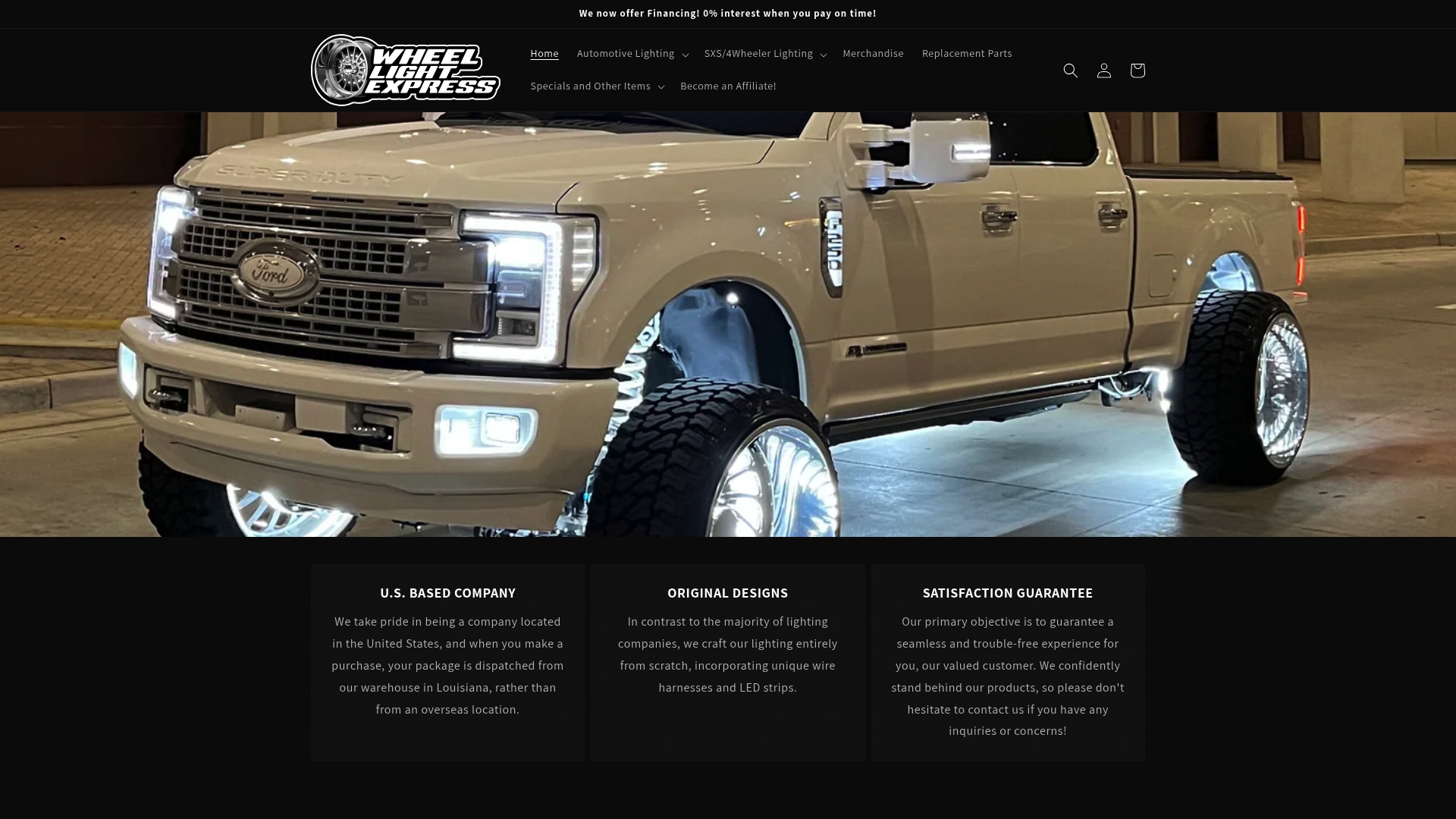
Browse our wheel light collection and back it with our satisfaction guarantee and financing options if you would rather skip the crimper and iron altogether.
FAQ
Is copper pipe crimping the same as wire crimping?
No, copper pipe crimping is a plumbing technique that compresses a fitting onto rigid pipe to form a watertight seal, while wire crimping compresses a terminal barrel onto stranded copper conductors to form an electrical connection. The two use different tools, different materials, and different acceptance criteria entirely.
What is crimping?
Crimping is a mechanical joining method that compresses a metal terminal around a stranded wire until the strands bond to the terminal wall without heat or solder. Done correctly, it forms a gas-tight connection that resists corrosion and vibration better than a loosely applied joint.
Does NASA solder or crimp wires?
NASA’s workmanship standard, NASA-STD-8739.4, governs both methods and specifies when each applies, prohibiting crimped contacts for solid wire and disallowing pre-tinned stranded wire in standard crimp terminals. Soldering remains standard for solder cups and circuit board work where the hardware is designed for it.
How do I crimp cables together?
Strip the wire to the terminal’s specified length, seat the strands fully in the barrel, then compress with a die-matched ratcheting crimper set to the correct height for that terminal and wire gauge. Follow up with a tug test and a visual check for bell mouth and even strand distribution before sealing with heat-shrink if moisture is a factor.
Should I choose crimp or solder for automotive LED wiring?
Crimping is generally the better choice for automotive LED wiring because it handles vibration and moisture better once sealed with adhesive-lined heat-shrink. Soldering still has a place for small repairs or connections at a PCB pad, but it is not the standard termination for harness-level automotive work.
Sources
- USCAR-21 Performance Specification | PDF | Electrical Connector | Specification (Technical Standard)
- WORKMANSHIP STANDARD FOR CRIMPING, INTERCONNECTING CABLES, HARNESSES, AND WIRING
- Automotive Wiring Repair - Solder, Crimp, and Splice Methods
- Heat Shrink Wire Connectors: Complete Guide for Automotive & Marine Wi – Binam Inc.