
Sequential lighting is defined as a system that activates multiple light segments one after another in a precise timed order, creating a directional sweep effect visible to other drivers. The industry term for this is “sequential turn signal” or “chasing light” technology, and it appears on factory vehicles like the Ford Mustang and Lincoln Continental as well as countless aftermarket builds. Understanding sequential lighting how it works gives you the technical foundation to retrofit your own vehicle or troubleshoot an existing setup. This guide covers the electronics, design variations, installation steps, and real benefits of sequential lighting technology for automotive use.
How does sequential lighting function technically in vehicles?
Sequential lighting works by dividing the lamp into multiple segments that activate in order during each blink cycle, producing a directional sweep from the inner edge of the lamp outward. Segment 1 lights first, then segment 2, and so on until the full signal is illuminated, then the cycle repeats. This is the core mechanic behind every sequential turn signal, whether factory-installed or DIY.
The timing logic that drives this sequence runs inside a microcontroller or relay-based control module. Sequencer logic advances through timed states, activating each output at intervals typically ranging from 100 to 500 milliseconds per step. That interval range matters because it determines whether the sweep looks smooth and deliberate or fast and aggressive. You can change the visual character of the animation entirely by adjusting the step delay in the controller firmware, without touching a single wire.

The most common animation pattern in automotive use is called “fill and hold.” The fill and hold pattern lights segments one by one until the full signal is on, holds briefly, then turns everything off and repeats. This matches the standard turn signal cadence drivers expect, so it reads as a legal indicator while still delivering the flowing visual effect.
Two separate time domains govern the whole system:
- The vehicle’s blink cadence (typically 60 to 120 flashes per minute, set by the flasher relay)
- The sequencer’s internal step timing (the interval between each segment lighting up)
Both must be managed independently. If your sequencer step timing is too slow relative to the blink cadence, the animation never completes a full sweep before the signal turns off. Getting these two domains in sync is what separates a polished build from a flickering mess.
Pro Tip: Before wiring anything, confirm whether your vehicle’s turn signal circuit switches a positive voltage or a ground signal. Vehicle signal polarity directly impacts how the controller interprets the trigger input, and getting it wrong causes unpredictable behavior or component damage.
Power, ground, and signal input handling are non-negotiable. A loose ground connection introduces resistance that causes uneven brightness across segments. A misidentified signal wire causes the sequence to fire at the wrong time or not at all. Treat every connection with the same care you would give a fuel system repair.
What are the key variations and designs in sequential lighting systems?
Not all sequential systems are built the same way. The architecture you choose affects cost, complexity, animation quality, and long-term reliability. Here is a direct comparison of the four most common approaches:
| System type | How it works | Best for | Limitations |
|---|---|---|---|
| Segmented LED arrays | Fixed LED groups wired to separate controller outputs | Clean factory-style builds | Less animation granularity |
| Addressable LED strips (WS2812B) | Each LED pixel controlled individually via data signal | Maximum animation flexibility | Higher programming complexity |
| Mechanical flasher + relay module | Relay-based sequencer triggered by OEM flasher | Simple retrofits on older vehicles | Limited timing precision |
| Microcontroller-based (Arduino, etc.) | Custom firmware controls all timing and patterns | Full DIY control | Requires coding knowledge |
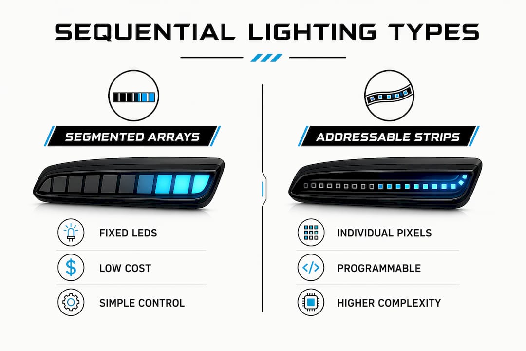
Segmented arrays reduce controller complexity because you are switching groups of LEDs rather than individual pixels. The tradeoff is animation granularity. A three-segment system produces a three-step sweep, which looks good but cannot replicate the pixel-by-pixel flow of an addressable strip. Diffuser design must complement segmentation for the best visual result, since a well-designed diffuser blends segment boundaries and makes the sweep appear smoother than the underlying hardware actually is.
Addressable strips like the WS2812B give you individual pixel control, which means you can program any pattern you want. The cost is a steeper learning curve. You need to write or adapt firmware, manage data signal integrity, and power the strip correctly to avoid color shift at the far end of the run.
Without a sequencer module, LEDs only flash on and off as a single unit instead of producing a flowing pattern. The control module is what converts a basic blink input into a multi-step animation. This is the single most important component in any sequential build, and skimping on it produces disappointing results.
Retrofitting older vehicles is generally straightforward because their wiring is simpler and they lack the diagnostic systems that complicate modern installs. Factory sequential systems on newer vehicles integrate with the CAN bus and are calibrated at the factory, which is why aftermarket replacements for those platforms require more careful component matching.
How do you install and troubleshoot sequential lighting in DIY automotive projects?
A clean installation follows a logical sequence. Rushing the wiring stage is the single most common reason DIY sequential builds fail.
- Identify your signal type. Use a multimeter to determine whether your turn signal wire switches positive voltage or ground. This tells you which input configuration your controller needs.
- Map your power and ground points. Run a dedicated ground wire to a clean chassis point, not a shared bolt with other accessories. Power the controller directly from the fuse box with an appropriately rated fuse.
- Wire the LED segments or strip to the controller outputs. Follow the controller’s pinout exactly. Label each wire before you tuck it away.
- Connect the signal input wire from your vehicle’s turn signal circuit to the controller’s trigger input.
- Test before final mounting. Activate the turn signal and confirm the sequence fires correctly, all segments illuminate evenly, and the animation completes within the blink cycle.
- Adjust step timing if needed. If the sweep looks rushed or incomplete, slow the step delay in the controller settings or firmware.
- Mount and secure all components away from heat sources and moving parts.
Pro Tip: Modern vehicles use CAN bus diagnostics that detect LED load differences and trigger bulb-out warnings. Load resistors or CANbus decoders resolve most of these errors by mimicking the resistance of a standard incandescent bulb. Install them in parallel with your LED load at each affected circuit.
For wiring reliability, a quality relay wiring kit protects your controller from voltage spikes and keeps current draw off the OEM signal wire. This is especially useful on older vehicles where the factory wiring is already carrying near its rated load.
Common troubleshooting issues and their fixes:
- Sequence fires in reverse order: Signal input and ground are swapped at the controller.
- Only one segment lights: A broken output trace or failed MOSFET on the controller board.
- Animation speed changes with engine RPM: Power supply is unregulated. Add a voltage regulator or use a dedicated 12V rail.
- Dashboard warning light for turn signal: Add load resistors or a CANbus-compatible decoder module.
- Flicker on all segments: Poor ground connection. Re-terminate the ground wire at a clean chassis point.
Correct wiring identification is the foundation of a reliable retrofit. Every other troubleshooting step assumes the basic wiring is correct, so verify it first before chasing other causes.
What are the aesthetic and safety advantages of sequential lighting?
Sequential lighting delivers real benefits beyond looking good on a show car. The directional sweep communicates turning intent more clearly than a static flash because the motion itself points in the direction of travel. Drivers behind you process a moving visual cue faster than a stationary one, which is the core safety argument for sequential signals.
Key benefits of sequential lighting in automotive applications:
- Improved visibility: The sweeping motion draws attention more effectively than a standard blink, particularly in heavy traffic or low-light conditions.
- Clear directional communication: The animation physically points in the direction of the turn, reinforcing the signal’s meaning.
- Modern styling: Sequential patterns give any vehicle a premium, contemporary appearance associated with high-end factory builds.
- Customization flexibility: Timing speed, segment count, and pattern type can all be adjusted to match your personal preference or vehicle style.
- Differentiation: A well-executed sequential build makes your vehicle stand out at shows and on the street without requiring body modifications.
Regulatory compliance is not optional. In the United States, turn signals must emit amber light at a specific intensity range to meet Federal Motor Vehicle Safety Standard No. 108. White or red sequential signals on the front or rear turn positions are not street legal regardless of how well they are built. Confirm your LED color and intensity meet FMVSS 108 before driving on public roads. Aftermarket sequential tail lights that use red for the turn function in a combined stop and turn lamp are also subject to specific brightness ratios. Check your state’s vehicle code for additional requirements.
For a deeper look at how different automotive LED technologies compare in terms of output and compatibility, that resource covers the hardware side in detail.
Key takeaways
Sequential lighting requires a dedicated control module, correct signal polarity identification, and synchronized timing between the vehicle’s blink cadence and the sequencer’s step intervals to produce a reliable, smooth animation.
| Point | Details |
|---|---|
| Core mechanic | Segments activate in timed order, typically 100 to 500 ms per step, to create a directional sweep. |
| Control module is required | Without a sequencer module, LEDs flash as a single unit with no animation effect. |
| Signal polarity matters | Identify whether your vehicle switches positive or ground before wiring the controller input. |
| CAN bus compatibility | Modern vehicles need load resistors or CANbus decoders to prevent bulb-out warning errors. |
| Legal compliance | US turn signals must emit amber light meeting FMVSS 108 intensity standards to be street legal. |
Why timing is the part most DIYers get wrong
I have reviewed a lot of sequential builds, and the most consistent mistake is treating the two timing domains as one problem. Builders spend hours on wiring and then program the sequencer step delay without ever checking whether the animation completes within the vehicle’s actual blink cycle. The result is a sweep that gets cut off mid-sequence, which looks worse than a standard blink.
The fix is simple once you know to look for it. Measure your vehicle’s blink cadence with a stopwatch or oscilloscope, then set your sequencer’s total animation time to roughly 70 percent of that duration. That leaves a clean off period between cycles and makes the sweep look intentional rather than interrupted.
Component selection is the other area where I see people cut corners. A cheap relay module from an unknown source might work for a week and then fail in a way that takes out your OEM flasher circuit with it. Spending a little more on a quality controller with documented specifications protects both your build and your vehicle’s factory wiring. The LED strip applications guide covers hardware selection in more depth if you want to go further on that topic.
The balance between aesthetics and compliance is real. A sequential build that uses the wrong color or exceeds legal intensity limits is a liability, not an upgrade. Build it right the first time and you get a mod that looks great and passes inspection.
— Christopher
Upgrade your build with Wheellightexpress
Wheellightexpress designs every product in Louisiana, which means you get lighting solutions built specifically for the demands of automotive enthusiasts, not generic imports. Their catalog includes LED strips and wire harnesses engineered for clean, reliable installs on a wide range of vehicles. If you are sourcing components for a sequential lighting project, the aftermarket lighting collection covers everything from LED strips to replacement harnesses. Wheellightexpress backs every purchase with a satisfaction guarantee and offers financing options so you can build the way you want without waiting. Browse the full catalog and find the right parts for your next build.
FAQ
What is sequential lighting in a car?
Sequential lighting is a turn signal system that activates multiple lamp segments in timed order to create a directional sweep effect. It is also called a chasing turn signal or animated turn signal.
How does a sequential turn signal controller work?
The controller receives the vehicle’s standard turn signal trigger and converts it into a multi-step output, lighting each segment at a set interval (typically 100 to 500 ms per step) before repeating the cycle.
Do I need a special module for sequential lighting?
Yes. Without a dedicated sequencer module, your LEDs will only flash on and off as a single unit. The module is what generates the individual segment timing that creates the animation.
Will sequential LEDs trigger a dashboard warning light?
On modern vehicles with CAN bus diagnostics, LED installations often trigger bulb-out warnings because of the lower electrical load. Load resistors or a CANbus-compatible decoder module resolve this in most cases.
Is sequential lighting legal on public roads in the US?
Sequential turn signals are legal when they emit amber light and meet the intensity requirements of FMVSS 108. Non-amber colors or incorrect brightness levels make the installation non-compliant for street use.