

3% Voltage Drop: Build an Expandable Wiring Harness for Lights
An expandable wiring harness is an adaptable wiring assembly that lets you add, remove, or reconfigure vehicle lighting circuits without tearing into the factory wiring every time your plans change. Builders use them for wheel lights, rock lights, portal lights, and light bars because one harness can grow with the vehicle. The main payoff is simple: you plan once, wire once, and add accessories later without a full rewire.
TL;DR:
- Keep voltage drop below 3% by sizing wire for circuit draw and measured run length; long rear runs and combined feeds need thicker wire.
- Fuse each new branch at roughly 125% of continuous current draw, and place the main fuse within about 12 inches of the battery terminal.
- Separate each lighting zone with plug groups and adaptor points; IP67 waterproof connectors, Y harnesses, and spare distribution ports let additions avoid cutting trunk wiring.
- FMVSS No. 108 bars modifications that impair required lamps; keep new lights on separate switched circuits and check the service manual before CANbus connections.
Table of Contents
- Electrical Specs You Need to Get Right: Wire Gauge, Voltage Drop, and Fuse Sizing
- Design Patterns That Make a Harness Actually Expandable
- Installing an Expandable Harness: A Step-by-Step Checklist
- Compatibility Check: FMVSS No. 108 and Your Vehicle’s Factory Systems
- Expanding an Existing Harness to Add New Lighting Modules
- Troubleshooting Common Wiring Harness Issues in Lighting Systems
- Materials and Tools for Building or Modifying an Expandable Harness
- Staying Safe During Installation: Electrical Hazard Prevention
- Why Planning for Expansion Early Pays Off
- Where to Go Next for a Harness That Grows With Your Build
- FAQ
- Sources
Electrical Specs You Need to Get Right: Wire Gauge, Voltage Drop, and Fuse Sizing
Before you cut a single wire, you need to know how much current your lights draw and how far that current has to travel. Add up the amp draw of every light on a circuit, measure the run length from the power source to the load, and work backward to the wire gauge that keeps voltage drop low. Most 12V lighting setups should target a 3% voltage-drop limit, which keeps lights bright and consistent even on long runs to the rear of a truck or trailer, according to practical 12V wiring guidance.
Here’s how that plays out on common lighting accessories:
- Short runs powering a single rock light pod often work fine on relatively thin wire gauges like 18 or 16 AWG.
- Longer runs to rear-mounted light bars or multiple wheel light zones generally require thicker wire gauges such as 14 or 12 AWG.
- Main feed wires from the battery to a distribution point should be sized for the full combined load, often needing wire gauges like 10 or 8 AWG on larger builds.
A voltage-drop problem shows up as dim lights, not a dead circuit. If your lights work but look weaker than expected, check voltage at the load while everything is running rather than at the battery with the engine off, a step emphasized in the same wire gauge and fuse guidance.
Fuse sizing follows its own rule: size the fuse at roughly 125% of the continuous current draw on that circuit, and place the main fuse within about 12 inches of the battery terminal, a safety practice outlined in our fuse sizing guide for LED lights. That placement limits how much unprotected wire exists between the battery and the first fuse, which matters if that wire ever chafes or shorts against the chassis.
Pro Tip: Wire every new lighting branch through its own fused circuit instead of tapping into an existing one, even if the existing circuit has spare capacity. It keeps future additions isolated and troubleshooting simple.
For systems with more than two or three lighting zones, a relay and a distribution fuse block do more work than individual inline fuses scattered across the harness. The relay carries the heavy switched load while a low-current wire triggers it from a switch or module, and the fuse block gives you one place to add a new circuit when you expand later.
Design Patterns That Make a Harness Actually Expandable
A harness only qualifies as expandable if its structure supports adding accessories without repinning the main feed or cutting into factory circuits. The patterns that make this possible borrow from how production vehicles build modularity into their own wiring.
- Segment the harness into self-contained plug groups. Each lighting zone, front, rear, rock lights, portal lights, gets its own connector group so a change to one zone never touches another.
- Build in an adaptor interface on the main trunk. A single main harness with a standardized connector lets you plug in different accessory types without altering the trunk wiring itself, an approach described in patent literature on modular harness design.
- Route sub-harnesses to isolated connector points rather than splicing mid-run. This keeps every future change at a connector, not a cut wire.
This segmented, adaptor-based structure is why production vehicles can offer optional lighting packages without redesigning the whole harness for each trim level, and it works the same way on a truck or off-road rig you’re building out over time.
In practice, this means stocking the right connector types:
- Y-harnesses split one power source to two accessories without cutting the main line.
- Extension pigtails lengthen a run when you relocate a light or add a zone further down the vehicle.
- Waterproof inline connectors rated IP67 handle splices exposed to mud, water crossings, and road spray.
- A small distribution bus centralizes power so new branches plug in rather than splice in.
Pro Tip: Use a heavier gauge wire for the main feed than any single branch needs. It costs a little more up front but means you won’t have to replace the trunk wiring the next time you add another lighting zone.
Strain relief and solid bracket mounting at every connector point matter just as much as the wire gauge and retrofit standards. A harness that flexes and tugs at its connectors will fail at the plug long before the wire itself wears out.
Installing an Expandable Harness: A Step-by-Step Checklist
A good install follows the same order every time: plan, route, secure, connect, test.
- Map every load first. List each light, its amp draw, and where it mounts, then total the draw per circuit before buying wire.
- Measure actual run lengths, not estimates, from the power source to each load point, and use those numbers to confirm wire gauge and fuse size.
- Choose mounting points for the distribution block, relays, and connector junctions before you route a single wire.
- Route along the chassis, away from exhaust heat, suspension travel, and moving steering components, and use rubber grommets anywhere wire passes through sheet metal.
- Make connections with proper crimps or solder joints, then seal with adhesive-lined heat shrink. Use waterproof connectors at every junction exposed to weather.
- Place relays close to the load they control to minimize the length of heavy switched wire.
- Bench test each segment before final mounting, confirming the fuse holds and the light reaches full brightness.
- Verify voltage at the load under real operating conditions, engine running, other accessories on, and watch for any CANbus warning lights on newer vehicles.
A few habits keep the system serviceable:
- Label every run at both ends before you button up the install.
- Leave a small service loop of extra wire at each connector in case you need to move a mount later.
- Inspect connectors and grommets every few months, especially after off-road use.
A fuse sized at roughly 125% of continuous draw, placed within about 12 inches of the battery, is the baseline safety practice for any added lighting circuit, per wire gauge and fuse sizing guidance.
Compatibility Check: FMVSS No. 108 and Your Vehicle’s Factory Systems
Before tying any new lighting into existing circuits, it helps to understand the federal framework that governs vehicle lighting. FMVSS No. 108 sets requirements for required lamps and associated equipment, covering mounting position, photometric output, and how replacement equipment must perform. It does not ban supplemental lighting outright, but it does prohibit modifications that impair the performance of required lamps.
That impairment standard, found at S6.2.1, is the practical line aftermarket builders need to respect. NHTSA has addressed this directly in an interpretation letter about a supplemental beam system that activates a backup lower beam only when a required lamp fails, noting that supplemental lighting is treated differently from required lighting based on factors like activation behavior and intended use.
A few compatibility habits keep you clear of that line:
- Avoid tapping into headlamp or taillight control circuits directly; use an adaptor interface instead.
- Keep supplemental lighting on its own switched circuit rather than piggybacking a required lamp’s wiring.
- On CANbus-equipped vehicles, check the service manual or consult a professional before connecting anything to a factory lighting module.
Supplemental lighting is permitted as long as it does not impair the effectiveness of lighting equipment required by Standard No. 108.
Expanding an Existing Harness to Add New Lighting Modules
Expanding a harness you’ve already installed is less work than starting over, as long as you planned for it. Start by confirming what capacity your existing distribution block and main feed have left. If the main feed was sized for future growth, you likely have margin to add another branch without upgrading the trunk wiring.
Next, identify the nearest adaptor point or spare connector on your segmented harness. If you built with plug groups, the new light simply taps into an open port on the distribution bus rather than splicing into live wire. If no spare port exists, add a Y-harness at the nearest junction to split power to the new accessory without disturbing the original run.
Size the new branch independently: calculate its amp draw, pick the wire gauge for that run length, and fuse it on its own circuit even if it shares a relay with an existing light. Route the new branch along the same path as its neighbors where possible, using existing grommets and brackets rather than creating new penetration points in the body.
Finish with the same bench test and load test used on the original install: confirm brightness, check voltage at the new load under operating conditions, and verify the existing lights still perform the same as before. A properly modularized harness means that last check should show no change at all.

Troubleshooting Common Wiring Harness Issues in Lighting Systems
Most lighting harness problems trace back to one of four causes: a bad ground, a loose or corroded connector, an undersized wire, or a blown fuse with an unaddressed root cause.

Start with the simplest check. If a light doesn’t come on, test the fuse first, then trace back to the connector nearest the light. Corrosion and loose pins cause more lighting failures than actual wire damage, especially on harnesses exposed to water crossings or road salt.
Flickering lights under vibration usually point to a connector that isn’t fully seated or a ground point that has loosened over time. Reseat the connector, and if the problem persists, check the ground wire’s terminal for corrosion or a loose bolt.
Dim lights that never reach full brightness, even with a good connection, almost always mean the wire gauge is undersized for the run length or the load has grown since the circuit was wired. Measure voltage at the load under operating conditions.
Repeated fuse failures on one circuit mean something is drawing more current than the circuit was designed for, whether that’s a new accessory added to an old branch or a short somewhere along the run. Don’t just size up the fuse. Find the actual cause first, since a larger fuse on a damaged wire removes the protection that fuse is there to provide.
Materials and Tools for Building or Modifying an Expandable Harness
A solid harness build starts with the right materials on hand before you cut anything.
- Primary wire rated for automotive use in the gauges your load calculations call for, typically 18 through 10 AWG for lighting circuits.
- Weatherproof connectors rated IP67 for any junction exposed to water or mud.
- Heat-shrink butt connectors or a crimp tool plus adhesive-lined heat shrink for sealed, durable splices.
- A fuse block or distribution bus sized for the number of circuits you plan to run, with room for future branches.
- Relays rated for the amp draw of your heaviest lighting circuit.
- Split loom tubing or braided sleeving to protect runs from abrasion along the chassis.
- Rubber grommets for every point a wire passes through sheet metal.
- A multimeter to verify voltage drop and confirm connections before and after final mounting.
A crimp tool rated for the connector type you’re using matters more than most builders expect. A poorly crimped connection looks fine on the bench but fails under vibration, which is exactly the condition an off-road harness lives in.
Staying Safe During Installation: Electrical Hazard Prevention
Disconnect the battery before starting any wiring work, including adding a single accessory to an existing harness. A short circuit while the battery is live can damage components or start a fire far faster than a short on a disconnected system.
Keep every splice and connector sealed against moisture, since a corroded connection doesn’t just fail, it can create resistance that generates heat at the joint. Route wiring away from exhaust components, moving suspension parts, and sharp edges where the insulation could wear through over time.
Never skip the fuse to simplify a circuit, even temporarily for testing.
Double-check polarity before powering up a new circuit for the first time, and test with a multimeter before connecting an expensive light module. A reversed connection on some LED fixtures causes immediate damage that a quick voltage check would have caught.
Why Planning for Expansion Early Pays Off
Most lighting projects grow over time. A builder who adds rock lights one season often adds portal lights or a rear light bar the next, and a harness designed for expansion from the start saves hours of rework down the road. Our wiring harnesses and LED lighting are made to include over-spec wiring and durable connectors that hold up as a build grows.
— Christopher
Where to Go Next for a Harness That Grows With Your Build
The wiring harnesses and lighting kits are built with a segmented, adaptor-friendly structure described in this guide rather than adapted from a one-size-fits-all import harness.
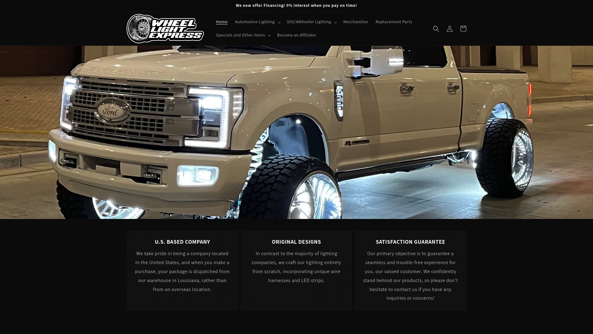
- Browse our wheel light collection if you’re planning a wheel-light run on your next harness branch.
- Check out our rock light collection for a common add-on accessory that pairs well with an expandable harness.
- Use our replacement wiring harness as a starting point if your current harness needs an upgrade before you expand it.
Every order comes with a satisfaction guarantee, and financing is available if you’d rather spread the cost of a full lighting setup across payments instead of paying it all upfront.
FAQ
What wire gauge should I use for an expandable lighting harness?
Shorter runs to a single accessory often work with 18 or 16 AWG, while main feeds carrying combined loads typically need 10 or 8 AWG, based on practical 12V wiring calculations.
How do I size a fuse for a new lighting circuit?
The guidance detailed in our fuse sizing guide protects the wire from overheating if a fault develops.
Can I add aftermarket lighting without affecting my factory headlamps?
Yes, as long as the new lighting doesn’t impair the performance of required lamps under FMVSS No. 108. The safest approach is to wire new accessories on their own switched circuit rather than tapping into existing headlamp wiring.
What connector types work best for a modular harness?
Waterproof inline connectors rated IP67 handle exposed splices, while Y-harnesses and extension pigtails let you add or relocate accessories without cutting the main trunk wire. A distribution bus centralizes these connections so new branches plug in rather than splice into live wiring.
Does Wheel Light Express sell harnesses that can be expanded later?
Yes, our wiring harnesses are designed and manufactured in-house in Louisiana with segmented wiring and adaptor interfaces built in, so adding a new lighting zone later doesn’t mean rewiring the whole harness. Pricing for our Solar Powered Cab Lights is $399, and our harness and lighting collections are available to browse directly on our site.
Sources
- 571.108–Supplement beam–Boykin–16-0884 | NHTSA
- eCFR :: 49 CFR 571.108 – Standard No. 108; Lamps, reflective devices, and associated equipment.
- 12V Wire Gauge & Fuse Calculator: Choose the Right AWG and Fuse Size - Auto Measurements
- Electrical connection arrangement connecting freely configurable vehicle components (patent review)