
Lighting best practices for custom builds are defined by three non-negotiable pillars: precise electrical design, verified component compatibility, and structured commissioning. Skip any one of these and you get flickering LEDs, voltage drop across long runs, or a wiring harness that fails under inrush current. Professional automotive lighting design, the industry term for what enthusiasts call “custom lighting solutions,” follows the same workflow used in commercial installations: schematic first, hardware second, testing last. Standards like SAE J1128, ISO 6722, and IES guidance exist precisely because the gap between a good-looking build and a reliable one comes down to planning.
1. How to plan the electrical blueprint for your custom lighting build
The electrical blueprint is the foundation of every successful custom lighting project. Before you buy a single LED strip or wire harness, you need to know your vehicle’s available power, breaker capacity, and the total current draw of every component you plan to install. This is where most builds go wrong. Enthusiasts pick hardware first and figure out power later, which leads to undersized circuits and blown fuses.
Start by mapping your mains distribution. List every lighting circuit you intend to run, assign a current draw value to each, and add 20% headroom for LED driver inrush current spikes that occur at power-on. Inrush can be three to ten times the steady-state current, which affects fuse behavior and voltage stability if you have not accounted for it.
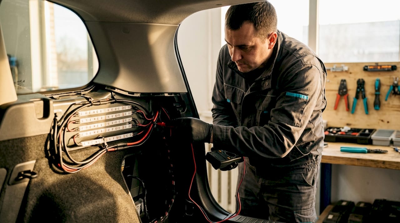
Staged commissioning is the professional method for validating your blueprint before full power-on. The process follows a specific sequence: power off all lights, activate the control network, then bring up dimmer and LED circuits one at a time. IES guidance recommends documenting channel maps and test logs at each stage so you can trace any fault back to its source without guessing.
Pro Tip: Size your fuses to the wire, not the load. If your wire is rated for 10A, fuse it at 10A regardless of whether the LED draw is only 4A. This protects the wire from a fault in the fixture.
2. Top hardware and wiring choices for even brightness and durability
Hardware selection determines whether your build looks professional or amateur six months after installation. The two most common mistakes are using generic wiring and daisy-chaining LED strip sections.
Wiring standards to follow:
- Use SAE J1128 or ISO 6722 rated wire for all automotive lighting circuits. These standards specify insulation thickness, temperature resistance, and conductor purity for automotive environments.
- Avoid copper-clad aluminum (CCA) wire. CCA has higher resistance than pure copper, which increases voltage drop across long runs and can cause heat buildup at terminations.
- Match wire gauge to run length and current draw. A 20-foot run at 5A needs heavier gauge than a 3-foot run at the same current.
- Never mix voltages in the same LED strip circuit. A 12V strip requires a 12V power supply; mismatching voltages creates fire hazards and premature LED failure.
Parallel wiring vs. daisy chaining:
| Wiring Method | Brightness Consistency | Fault Isolation | Recommended |
|---|---|---|---|
| Parallel to controller | Even across all sections | Yes, one section fails independently | Yes |
| Daisy chain | Drops toward end of run | No, one fault affects all | No |
Running LED sections in parallel back to the controller maintains equal voltage at every section. Daisy chaining creates cumulative voltage drop that dims the sections furthest from the power source.
Pro Tip: When sourcing LED strips for your build, check the lumen output ratings before purchasing. Two strips with identical wattage can produce very different brightness levels depending on LED chip quality.
Dimmer compatibility is a separate issue that catches many builders off guard. LEDs labeled “dimmable” do not work reliably with every dimmer type. Leading-edge TRIAC dimmers frequently cause flicker and hum with LED drivers. You need a trailing-edge or LED-specific dimmer matched to the driver’s load range.
3. Managing voltage drop for optimal lighting performance
Voltage drop is the single most underestimated problem in custom automotive lighting builds. It causes brightness inconsistency, color shift in RGB strips, and premature LED failure. The standard limit for branch lighting circuits is approximately 3% voltage drop from source to fixture. On a 12V system, that means you cannot afford to lose more than 0.36V across the run.
Three variables control voltage drop: wire gauge, run length, and current draw. Increasing any one of them raises the drop. The practical fix is to use heavier gauge wire on longer runs, or to place sub-distribution points closer to the load. A sub-distribution point is a secondary power connection point fed directly from the battery or fuse block, which shortens the effective run length for each branch.
| Run Length | Current Draw | Minimum Wire Gauge (12V system) |
|---|---|---|
| Up to 5 ft | 3A | 18 AWG |
| 5 to 10 ft | 3A | 16 AWG |
| 10 to 20 ft | 5A | 14 AWG |
| Over 20 ft | 5A | 12 AWG |
Voltage drop planning is especially critical in custom wiring harnesses where run lengths grow as you route wire around body panels and through door jambs. Calculate drop before you cut wire, and recalculate after any layout change. A free online voltage drop calculator takes less than two minutes and saves hours of troubleshooting.
4. Ensuring professional commissioning and maintenance
Commissioning is not a formality. It is the process that confirms your build works as designed before you close up panels and call it done. A structured commissioning sequence prevents the most common post-installation failures.
- Power off all lighting circuits before connecting the control network. This prevents accidental energizing of circuits during addressing.
- Activate the control network (DMX512, PWM controller, or analog dimmer) and verify addressing. Confirm each channel responds to the correct control signal.
- Bring up LED and dimmer circuits one at a time. Check for flicker, unexpected dimming behavior, or heat at terminations.
- Run a full functional test. Cycle through all programmed scenes or color modes and verify output matches your design intent.
- Document everything. Record channel maps, firmware versions, and test logs for every circuit. This documentation is what lets you diagnose an intermittent fault six months later without starting from scratch.
Maintenance schedules matter as much as the initial build. Write down a quarterly inspection checklist that covers termination integrity, fuse condition, and firmware currency. Commissioning documentation and operator training significantly reduce operational downtime in complex LED systems. If someone else works on your vehicle, that documentation tells them exactly what they are looking at.
5. How to achieve the right balance of brightness, uniformity, and glare control
Professional lighting designers set measurable performance goals before selecting any hardware. This approach applies directly to custom automotive builds. Without targets, you end up with fixtures that look good in isolation but create hot spots, dark zones, or glare that makes the vehicle uncomfortable to be around at night.
Set these targets before you buy anything:
- Minimum and maximum lux levels at key surfaces (wheel wells, undercarriage, interior panels)
- Uniformity ratio: the difference between the brightest and darkest point in a lit zone
- Glare control: mounting angle and shielding requirements to prevent direct view of the LED source
Photometric simulation tools like DIALux allow you to model your lighting layout digitally before committing to hardware. You input fixture specifications, mounting positions, and surface reflectances, and the software calculates predicted lux levels and uniformity. Starting with measurable targets before selecting hardware prevents uneven coverage and costly rework.
Mounting angle and spacing are the two physical variables that control uniformity and glare. For underbody lighting, angling strips inward toward the vehicle’s centerline reduces direct glare to onlookers while maintaining even ground illumination. For wheel well lighting, spacing strips at consistent intervals around the arch prevents the bright-spot-and-shadow pattern that makes amateur builds obvious.
Pro Tip: Validate your photometric simulation on site with a simple lux meter before finalizing mounting positions. Real-world surface reflectances differ from simulation defaults, and a 15-minute field check can save you from remounting fixtures.
The lighting design process used by professionals moves from schematic and photometric calculations to specification and then commissioning. Following this sequence aligns your real results with your simulations and eliminates guesswork at every stage. You can explore the full range of automotive LED types to match fixture choices to your photometric targets.
Key takeaways
Successful custom automotive lighting builds require upfront electrical planning, parallel wiring topology, voltage drop budgeting within 3%, and documented staged commissioning to deliver consistent brightness and long-term reliability.
| Point | Details |
|---|---|
| Plan the electrical blueprint first | Map current draws including inrush before selecting any hardware or wire gauge. |
| Wire in parallel, not series | Run LED strip sections back to the controller in parallel to maintain even brightness across all zones. |
| Budget for voltage drop | Keep branch circuit drop at or below 3% by matching wire gauge to run length and current. |
| Commission in stages | Power up control networks before LED circuits and document every channel map and firmware version. |
| Set photometric targets early | Define lux levels and uniformity ratios before sourcing fixtures to prevent costly rework. |
What I’ve learned from real custom builds that most guides skip
I’ve reviewed a lot of custom automotive lighting builds, and the pattern that separates the ones that hold up from the ones that fail within a year is almost never the LED strip choice. It is the compatibility between the control system, the dimmer, and the LED driver. Builders spend hours picking the right color temperature and IP rating, then wire a leading-edge TRIAC dimmer to an LED driver that needs a trailing-edge signal. The result is a flicker that shows up only at certain dim levels and takes days to diagnose.
The second most common oversight is inrush current. A wiring harness that handles steady-state current perfectly can still blow fuses at power-on because nobody calculated the inrush spike. SAE J1128 rated wire and properly sized fuses solve this, but only if you do the math before you build.
The tip I give every builder who asks: document your commissioning steps as you go, not after. Write down the channel address, firmware version, and test result for each circuit the moment you confirm it works. I have seen builds where a single undocumented firmware update caused a control conflict that took three days to trace. A one-page log would have cut that to ten minutes.
Layered lighting is worth the extra planning effort. Combining underbody strips, wheel well accents, and interior ambient lighting creates depth that a single-zone build cannot match. The key is treating each layer as an independent circuit with its own power budget and control channel, so you can adjust or troubleshoot one layer without affecting the others.
— Christopher
Build smarter with Wheellightexpress
Wheellightexpress designs every product in Louisiana specifically for automotive enthusiasts who want original, reliable lighting builds. Their catalog covers the full range of what a custom build needs: LED strips and ring kits, purpose-built wire harness leads, and replacement harnesses sized for automotive environments. Every product ships with a satisfaction guarantee, and financing options mean you can build the setup you actually want without compromising on components. If you are sizing your build, the wheel light sizing guide walks you through matching strip length and harness specs to your specific vehicle. Wheellightexpress makes it straightforward to get the right parts the first time.
FAQ
What is the most common cause of LED flicker in custom builds?
Dimmer and driver incompatibility is the leading cause of LED flicker. Leading-edge TRIAC dimmers frequently cause flicker with LED drivers that require trailing-edge signals, even when the LED strip is labeled dimmable.
How do I prevent voltage drop in long LED strip runs?
Use heavier gauge wire on longer runs and place sub-distribution points closer to the load. Keeping branch circuit voltage drop at or below 3% on a 12V system maintains consistent brightness and color stability across all sections.
What wiring standard should I use for automotive lighting?
SAE J1128 and ISO 6722 are the correct standards for automotive lighting wire. These ratings cover insulation temperature resistance and conductor purity, and they account for the inrush current spikes that affect fuse behavior at power-on.
Why should I wire LED strips in parallel instead of daisy chaining?
Parallel wiring delivers equal voltage to every strip section from the controller. Daisy chaining creates cumulative voltage drop that dims sections furthest from the power source and makes fault isolation impossible without disconnecting the entire run.
What should I document after commissioning my custom lighting build?
Record channel addresses, firmware versions, power schedules, and functional test results for every circuit. This commissioning documentation is the fastest way to diagnose intermittent faults and reduces troubleshooting time significantly on complex builds.